| | AS INTERFACE COMP. MODULE K60, DIGITAL, 4I, IP67, 4 X 1 INPUT, MAX. 200 MA, PNP, 4 X M12 STANDARD SOCKET Y-II ALLOCATION ATEX EX II 3D T60 C IP65X OBSERVE SPECIAL CONDITIONS FOR SAFE OPERATION: SUITABLE PROT. MEASURES AGAINST MECHANICAL DAMAGE REQUIRED. DETAILS SEE OPERATING INSTRUCTIONS ORDER MOUNT. PLATE 3RK19010CA00 SEPARATELY |
| |
| General technical data: |
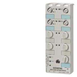
| Design of the product | | digital I/O modules for operation in the field, IP67 - K60 |
| Type | | 4 inputs |
| Design of the slave type | | standard slave |
| I/O configuration | | 0 |
| ID/ID2 code | | 1/F |
| Number / I/O sockets | | 4 |
| Design of the electrical connection / of the inputs and outputs | | M12 screw-type terminals |
| AS interface / total current input / max | mA | 270 |
| operating voltage | | |
- according to AS-Interface spezification
| V | 26.5… 31.6 |
| Ground terminal | | PIN5 of each M12 socket is connected to the grounding wrist strap in the mounting plate using a pin |
| Addressing | | front addressing socket |
| Application | | Use in Zone 22 hazardous areas according to Classification II 3D (dusty atmosphere, non-conductive dust), resistance to shock: 1 joule Conformance with Directive 94/9/EC (ATEX) is verified through compliance with the standards EN 50281-1-1 und EN 60947-5-2 |
| Delivery note | | the modules are delivered without mounting plate |
| Note 1 | | All K60 compact modules are delivered with stainless steel screws/sockets |
| |
| Sensor supply: |
| Type of voltage supply / for the sensor supply | | using AS-Interface |
| Input voltage | V | 20… 30 |
| Characteristic feature of the sensor supply / short-circuit and overload resistant | | Yes |
| Current carrying capacity / of the sensor supply / for all inputs | | |
- at ambient temperature 40 °C
| mA | 200 |
| |
| Inputs: |
| Number of digital inputs | | 4 |
| type of the connection technology | | 2 and 3-conductor technology |
| Input circuit | | PNP transistor |
| Type of voltage / of the input voltage | | DC |
| Inputs / switching level High / min | V | 10 |
| Input current / at the digital input | | |
| | mA | 6 |
| | mA | 1.5 |
| Inputs | | |
- sensor supply using AS-Interface
| | short-circuit and overload resistant |
| | | |
| | | sensor supply L+ |
| | | data input II |
| | | sensor supply L- |
| | | data input I |
| | | ground terminal |
| Design of the pin assignment / of the inputs | | Y-II assignement |
| |
| Outputs: |
| Number of digital outputs | | 0 |
| Outputs / external power supply 24 V DC | | not required |
| Outputs | | |
| | | not required |
| |
| Assignment of the data bits: |
| Assignment of data bits | | |
| | | PIN 4 = IN1 (D0), PIN 2 = IN2 (D1) |
| | | PIN 4 = IN2 (D1) |
| | | PIN 4 = IN3 (D2) , PIN 2 = IN4 (D3) |
| | | PIN 4 = IN4 (D3) |
| | | not assigned (closed) |
| | | not assigned (closed) |
| | | not assigned (closed) |
| | | not assigned (closed) |
| |
| Ambient conditions: |
| Ambient temperature | | |
| | °C | -25… 85 |
| | °C | -40… 85 |
| Protection class IP | | IP65 |
| |
| Status display: |
| Status display / display of I/Os | | yellow LED |
| Status display / display of Uaux | | not required |
| Status display / display of AS-Interface/diagnostics | | green/red LED |
| |
| Mechanical design: |
| Width | mm | 60 |
| Height | mm | 152 |
| Depth | mm | 29 |
| Type of mounting | | standard rail mounting/wall mounting using mounting plate for K60 compact module |
| |
| Certificates/approvals: |
| AS-Interface certificate | | yes (or requested for in case of new units) |
| Approvals | | UL, CSA, shipbuilding (or requested for in case of new units) |
| Explosion protection category for dust | | (Ex) II 3D Ex tD A22 IP65X T60°C |
| Limiting conditions for safe operation | | Suitable measures must be taken to protect the module from mechanical damage. All M12 connectors must be secured by a lock-clip against unauthorized opening such that the connector cannot be disconnected by hand but only by destroying the lock-clip. A suitable lock-clip is available from Binder GmbH + Co., Elektrische Bauelemente KG, Postfach 1152, 74148 Neckarsulm, Germany, Tel. +49 (0)7132/325-0, Fax +49 (0)7132/325-150, info@binder-connector.de, Article No. 16-0977-000. All the M12 sockets which are not assigned must be closed with 3RK1 901-1KA01 caps (tamper-proof version) such that they cannot be released by hand. Addressing the module using the 3RK1 904-2AB01 addressing unit is only permitted outside the EX-Zone 22. When the addressing operation is finished, the addressing socket must be closed with a 3RK1 901-1KA01 sealing cap (tamper-proof version) such that it cannot be released by hand. If an additional supply (AUX POWER) is required, it must comply with VDE 0106 (PELV), protection class III. |
| Safety and commissioning instructions | | The devices are approved for an ambient temperature of -25 to +85 °C. The devices must be configured, connected and commissioned by qualified, responsible personnel only. An incorrect response may cause serious injury to persons and damage to property. It is assumed that personnel are familiar with the assignment of classes to the permitted hazardous zones. The plug connectors and AS-Interface cables must not be connected or disconnected when live. The units require no maintenance. No modifications or repairs are allowed to be carried out on the units. All the above points must be observed in the event of replacement. See also Regulations for Installation EN 60079-14 / EN 50281-1-2. |
| |
| | |
| | |
| |
| last change: | Oct 31, 2011 |